Inductors may also be called chokes or coils. The impedance of the loudspeaker on the secondary coil of the transformer will be transformed to a higher impedance on the primary coil in the circuit of the power pentodes by the square of the turns ratio which forms the impedance scaling factor.

Aaronscher Com Resonant Coupling Networks

Transformer Coupled Front End For Wideband A D Converters

Custom Transformers Inductors Design Production 800 628
The reason for specifying a impedance is that the transformer is designed to have a adequate frequency response down to a load of 600.

Impedance inductor transformer. Impedance is the total resistance to current flow in an ac circuit containing both resistance and inductive reactance. The first term in eq 4 is due to leakage flux and the second term indicates the transformer action. The phase angles in the equations for the impedance of capacitors and inductors indicate that the voltage across a capacitor lags the current through it by a phase of while the voltage across an inductor leads the current through it by.
The inductive reactance of the winding must be higher than or equal to 600. Inductors have higher impedance to higher frequency signals. If we divide the sides of the voltage triangle above by the current another triangle is obtained whose sides represent the resistance reactance and impedance of the coil.
The impedance calculated is a measure of the inductors resistance to a signal passing through. An elementary transformation that can be done with ideal transformers and some other impedance element is to shift the impedance to the other side of the transformer. A quarter wave impedance transformer often written as l4 impedance transformer is a transmission line or waveguide used in electrical engineering of length one quarter wavelength l terminated with some known impedance.
It presents at its input the dual of the impedance with which it is terminated. In general a toroidal inductortransformer is more compact than other shaped cores because they are made of fewer materials and include a centering washer nuts and bolts resulting in up to a 50 lighter weight design. Omega at the lowest frequency of interest.
This means that lower frequency signals will have lower impedance or resistance. And conversely they have lower impedance to signals of lower frequency. If the coupling between two inductors is perfect coupling coefficient is unity and they behave like ideal transformer with turns ratio of 1n.
The identical voltage and current amplitudes indicate that the magnitude of the impedance is equal to one. Electromagnetic induction is at the heart of inductor theory of operation. This is especially the case for power devices.
The term choke refers to how inductors can be used to suppress undesired frequencies. In all the following transforms r is the turns ratio of the transformer.

Coupled Inductors As Transformer Analog Rf Intgckts

Transformer Loading And On Load Phasor Diagrams

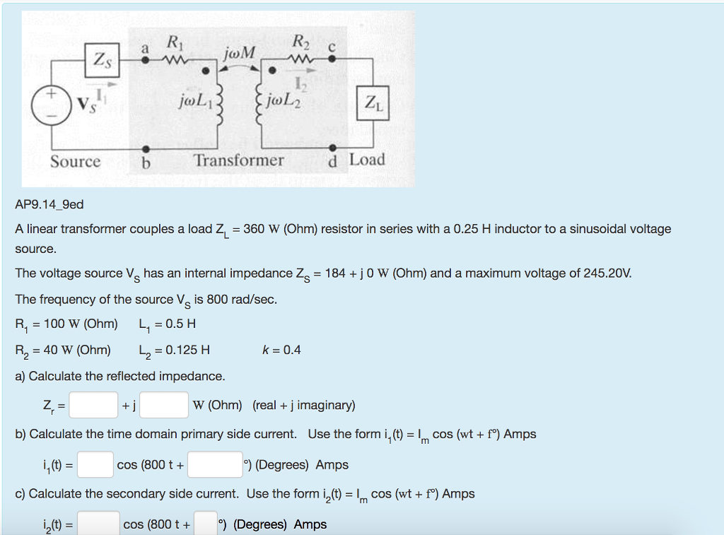
Solved A Linear Transformer Couples A Load Z L 360 W O

Coupled Inductors As Transformer Analog Rf Intgckts

Ve7cnf 630m Antenna Matching Measurements Using An

Inductance Of Rf Cored Inductors And Transformers

Quarter Wave Impedance Transformer Wikipedia

Toroidal Inductors And Transformers Wire Impulsstrafo

Inductive Reactance Reactance Of An Inductor

Using Transformers In Ltspice Switcher Cad Iii Analog Devices

Taiwan Smd Balun Transformer From Yangmei Manufacturer Abc

Spt 176 Ul 600w Primary Impedance Single Hybrid Transformer
Comments
Post a Comment