High Pass Filter Op Amp Calculator

This means that the output signal is 180 degrees out of phase with the input signal. The first part of this circuit comprised of resistor r1 and capacitor c1 compose the high pass filter.

Filter Design Guide

Filter Design Guide

Sallen Key Low Pass Butterworth Filter Calculator
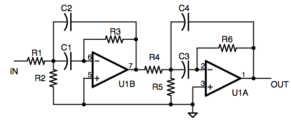
Sallen Key Low Pass Butterworth Filter Calculator

Dale S Homemade Robots Bandpass Filter Calculator

Dale S Homemade Robots Bandpass Filter Calculator

Thi op amp bandpass filter produces a noninverting signal at the output.


Dale S Homemade Robots Bandpass Filter Calculator

High pass filter op amp calculator. Value of the filter capacitor c1 c2. This means that the output signal is exactly in phase with the input signal. Then the active high pass filter has a gain a f that increases from 0hz to the low frequency cut off point f c at 20dbdecade as the frequency increases.

This op amp high pass filter produces an amplified inverting signal at the output. Ebn ee times electronic. Inverting op amp high pass filter active this calculator is for an active inverting op amp high pass filter.

It is one of the most widely used filter topologies. The sallen key filter is a simple active filter based on op amps stages which is ideal for filtering audio frequencies. By using this op amp based active high pass filter we can achieve high accuracy with the use of low tolerance resistors and capacitors.

One reason for its popularity is that this configuration shows the least dependence of filter performance on the performance of the op amp. At f c the gain is 0707a f and after f c all frequencies are pass band frequencies so the filter has a constant gain a f with the highest frequency being determined by the closed loop bandwidth of the op amp. We know that the active high pass filter can be designed by using either inverting terminal or the non inverting terminal of an operational amplifier.

This calculator is for an active noninverting op amp bandpass filter. Home tools op amp high pass butterworth filter calculator op amp high pass butterworth filter calculator. Active high pass filter using inverting operational amplifier.

Active High Pass Filter Circuit Design And Applications

Active High Pass Filter Circuit Design And Applications

Sallen Key Low Pass Filter

Sallen Key Low Pass Filter

Op Amp High Pass Active Filter Circuit Electronics Notes

Op Amp High Pass Active Filter Circuit Electronics Notes

Op Amp Low Pass Butterworth Filter Calculator Electronic

Op Amp Low Pass Butterworth Filter Calculator Electronic

Band Pass Stop High Pass And Low Pass Filter Full

Band Pass Stop High Pass And Low Pass Filter Full

How To Build An Active High Pass Filter Circuit With An Op Amp
How To Build An Active High Pass Filter Circuit With An Op Amp

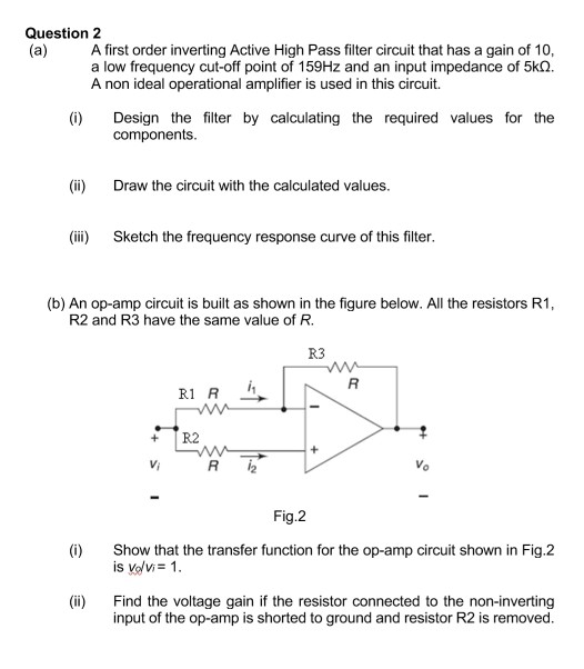
Solved Question 2 A A First Order Inverting Active High

Solved Question 2 A A First Order Inverting Active High

Active High Pass Filter Op Amp High Pass Filter

Active High Pass Filter Op Amp High Pass Filter

Filter Circuits With Capacitors

Filter Circuits With Capacitors

Active Low Pass Filter

Active Low Pass Filter

Active High Pass Filter Op Amp High Pass Filter

Active High Pass Filter Op Amp High Pass Filter

High Pass Filter Calculator

High Pass Filter Calculator

Comments

Popular posts from this blog

Diode T3d Datasheet

China Smd Zener Diode China Smd Zener Diode Manufacturers Practical November Panasonic Zener Diodes Panasonic Industrial Devices Shamim Pakzad Editor Proceedings Of The 36th Imac A T3d 98 Diode T3d White Imported Panasonic Plasma Tv Zener Diode Voltage Regulator China Smd Zener Diode China Smd Zener Diode Manufacturers 5 1v Zener Diode Everlight Elec Everlight Elec 16s 216 T3d Jp2r1qy 3t Light Tc 320 Service Manual H 01 Rohs 2 Rf2001t3d Datasheet Datasheet Pdf Info 7343 2surc H2 S400 A8 Datasheet Light Emitting Diode 5 Mm China 1w Zener Diode China 1w Zener Diode Manufacturers And

Draw Equivalent Circuit Zener Diode

The graph shows that the voltage remains constant even after the variation of the current. Electronics lectures by gulshan sinha 1554 views. Simplified Equivalent Circuit Of A Peo Load For Positive And C Hapter 2 Diode Applications What Is The Piecewise Linear Diode Model Quora There is an access resistance connected in series with an ideal diode d. Draw equivalent circuit zener diode . For ideal diode. This is the complete equivalent circuit for the device for all dc calculations. Simply means that it connects to other circuit elements at connection points labeled a and b in the circuit below with the voltage v ab applied across the diode. The zener voltage regulator consists of a current limiting resistor rs connected in series with the input voltage vs with the zener diode connected in parallel with the load rl in this reverse biased condit

Diode Iv Curve With Temperature

I know that these can modeled using the diode current equation. A pn junction diode is formed when a p type semiconductor is fused to an n type semiconductor creating a potential barrier voltage across the diode junction the effect described in the previous tutorial is achieved without any external voltage being applied to the actual pn junction resulting in the junction being in a state of equilibrium. Why Does Temperature Modify The Characteristics Of A Diode Zener Diode Basic Operation And Applications Curve Tracing Faq S Seaward Group Usa As its name suggests i v characteristic curves show the relationship between the current flowing through an electronic device and the applied voltage. Diode iv curve with temperature . Note that although you can simply vary the temperature and ideality factor the resulting iv curves are misleading. As expected the curve